Misalignments can cause machine downtime and significantly decrease machine performance; however, portable CMMs such as laser trackers and measuring arms can help to mitigate these issues.
The FARO Laser Tracker is ideal for many tasks such as machine tool alignment, roller and press alignment, jig and fixture alignment or CMM alignment. This accurate and fast method reduces downtime, improves quality and generates a proper trend analysis of distortion and other changes in a machine’s operation.
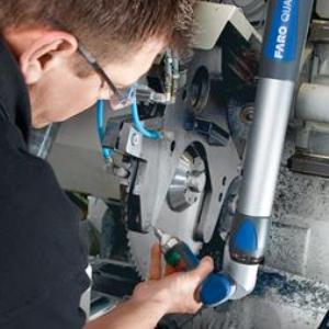
For smaller scale tasks, such as on-machine alignment, portable CMMs, such as the FaroArm is an ideal solution to complement the laser tracker work.
Croatian innovation from clay to metal products
Many articles have been written highlighting the revolution from bricks and mortar businesses to online shopping, but this is a story of a company that developed a brick that saves mortar, and then reinvented itself to become a metal products manufacturer with a global client base. It is a story of Croatian innovation.
The common thread in the activities of EKO MEĐIMURJE d.d. is making things better by making them simpler – that’s why they created interlocking oversized house bricks, which save clay, mortar and brick-laying effort. Besides the brick-making plant, the company also has a retail home and garden centre. But when the real estate crisis hit Europe, EKO MEĐIMURJE d.d. wasn’t caught off-guard.
Having developed their own engineering capabilities to update their brick plants, they already had relationships in other industries and an active development department working on new ideas in the area of metal work and machining. Today, EKO has renowned global players like Liebherr, Caterpillar, Wirtgen and Komatsu on their customer list.
![]()
Zoran Zdolec, Manager of electrical facilities at EKO MEĐIMURJE, explains “We use ProEngineer CAD software to design the product in accordance with the customers requirements. Then we use modern metal forming tools to create all the parts.” EKO recently invested in two FARO devices, a Laser Tracker ION and a FaroArm Fusion accompanied by FARO CAM2 Measure 10 software and thre
e weeks of training with Filip Donlic from Teximp d.o.o.– the FARO reseller for Croatia, Bosnia and Serbia. “Thanks to this investment EKO now has the latest in measuring tools for quality control and product documentation.”
Besides the documentation and quality control uses, EKO made one ROI calculation that really contributed to the investment decision. EKO has a SHW milling machine that is used for large parts. The milling head was equipped with a Renishaw measuring head. When parts were being aligned prior to machining using the Renishaw head, the machine is at a standstill and this process could take up to two hours for a very large part.
Filip Donlic was visiting the factory and saw that there is enough room on the machine table to begin alignment of a second part while the first part is still being milled. He recommended a FARO Laser Tracker ION for this process. “By overlapping the process of parts alignment and part milling, EKO is now saving around five hours of production time per day on this capital-intensive machine,” explains Donlic with satisfaction.
The FARO ION is now used to ensure that each part is perfectly aligned with the machine axis while another part is being finished. Once the milling head is free, the Renishaw can be used to collect a couple of reference points, but this only takes a couple of minutes.
The SHW machine operators are not metrologists, and they work in pairs in three shifts. So the solution had to be very simple to learn and to use: Donlic created an in-software app in CAM2 Measure 10. Now operators can simply follow the on-screen instructions and reference points on the edges of the piece until the app approves the position that has been set.
EKO also uses a FaroArm Fusion for general quality control tasks on its own or in conjunction with the Laser Tracker ION when checking large parts or on parts where features obscure the laser line of sight.
The contours, charisma and creation of supercars
Automotive Inspired by Italian renaissance heroes, legendary car designer Horacio Pagani creates the world’s most exclusive supercars by a masterful fusion of manual craftsmanship and technology.
The Argentinian-born designer Horacio Pagani, has risen to the top of supercar industry making a name for himself through his application of advanced composite materials. At Lamborghini, he worked on the designs of various famous models before founding Modena Design and starting work on his lifelong dream – the Pagani Zonda. Between 1999 and 2011, 206 variations of the Zonda were created and built. In 2011, Pagani revealed his new Huayra. It is a stunning curvaceous creation that is to many eyes, the fulfillment of Pagani’s dream to create the most beautiful car in the world. While championing a commitment to renaissance artists and hand craftsmanship, Pagani is firmly settled in the 21st century when it comes to metrology: the company owns two FaroArm Fusion systems. It also has one FARO Laser Line Probe that can be attached to either measuring arm to provide seamless Laser ScanArm functionality. With these systems, Pagani is perfectly equipped for free form surface measurement, part inspection, part-to-CAD comparison, rapid prototyping and reverse engineering.

Horacio Pagani, you started as a one-man design studio making furniture over 20 years ago. What elements of your approach have stayed constant?
Firstly, when I was about 16, I started learning about Leonardo and the Renaissance. I was fascinated by the way he mixed art and science and I wanted to do the same: to be both an artist and an engineer. That has been the consistent theme throughout my professional life. Secondly, I have always admired plastics because they allow you to be more expressive as a designer. I realised the significance of advanced composites in the eighties and we have been investing in applications of that technology ever since.
Tell us about the mixture of inspiration and technology behind your design process.
The female body was clearly a source of inspiration for the shapes of the Zonda. We work manually in the early stages with pencils and resin models. There is a charm that only the hand can give. When we have the cosmetics perfected, we use FARO 3D portable measuring systems and move into the CAD realm to deal with structural calculations and progress towards CAM.
There are 3 FARO devices in operation in your workshops. What other roles do they play?
We design and build our cars from scratch and we now manage about 10,000 distinct components. We use FARO arms and the Laser Line Probe for all kinds of tasks from reverse engineering during design to inspection and alignmentduring construction. They are an integral part of everything we do.
What new ambitions fuel your vision today?
I still work on many different projects covering automotive, aviation, military, sports and industrial design. Discovering new materials and new technologies still fascinates me.
FARO Laser Tracker integrated into the ESS Bilbao particle accelerator
ESS Bilbao is a technical scientific facility facing the challenge of constructing the first high-intensity linear accelerator in Spain. This is currently the most important scientific project in the Basque Country, as well as being a prominent European model for particle accelerator technology. The FARO Laser Tracker ION is integrated into the entire accelerator system, has become a fundamental instrument in this ambitious project. It is currently the indispensable solution for providing measurements in the field of metrology and for the alignment of the accelerator with maximum precision in 3D.
The FARO Laser Tracker ION is a portable measurement system that uses a laser beam to measure the coordinates of large components, equipment and machines in 3D using a spherical reflector. The ION has a measurement volume of 110m and uses aADM (Agile Absolute Distance Measurement) – the fastest system for calculating a position in 3D in real time.
In ESS Bilbao, this FARO product is integrated into the entire accelerator system to measure the components and mechanical parts of the accelerator and to align all of its sections. The FARO Laser Tracker ION not only enables rapid measurements, but can also scan surfaces. Maintaining precision at long distances from the target being measured is considered indispensable and is only possible with a device that has these characteristics.
Carlos Martínez de Marigorta explains: “The particle accelerator has different applications, for example in radiobiology (study of the effect of radiation on biological samples), materials (structural materials in fusion plants), electronic components (aerospace), etc. With regard to applications in the area of generated neutrons, the ones that stand out are laboratories that work with neutron ‘scattering’ (which would be used by the scientific and industrial community) and neutron time of flight.” He also maintains that the FARO Laser Tracker is an essential system in any accelerator in order to be able to align its components.
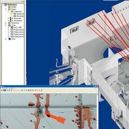
 As can be seen in Figure 1, the FARO Laser Tracker ION and its powerful software are currently being used for the alignment of the different vanes (segments from which this particular component is formed) of the Radio-Frequency Quadrupole (RFQ) “cold model” or prototype. This component accelerates and focuses the “bunch” or group of protons due to the potential difference created between its vanes.
In this current application, the FARO Laser Tracker ION is used to take measurements at various points of the different vanes in the RFQ to check the difference in position between them (all of the vanes need to be aligned), as the difference between the vanes should not be more than a few microns.
One way of checking that this has been achieved is to move the Laser Tracker to another position and again take the measurements at the same points of each vane at which they were taken previously. The results should be the same. (Figure 2).

The steel component that can be seen in Figure 1 is the RFQ cold model, composed of four segments (upper, right, left, lower) called vanes. The Laser Tracker is used when trying to align them in such a way that none of the vanes is projecting compared to the others in any of their planes.
 A Laser Tracker device takes a measurement by emitting a laser beam that is reflected in a reflector (SMR of 0.5’ in this case), which means that the position is measured with great precision.
The image in Figure 2 is taken from the software used to carry out the relevant calculations, which graphically highlights the work done on the RFQ (in this case) and the position of the Laser Tracker in a real situation.
This advanced software displays icons that really look like the devices (Laser Tracker, measurement arms, etc.) to make it simpler to understand each device. The 3D representation of the parts can be imported in any type of design format.
Perfect Alignment for Steel and Aluminium Mills at Siemens with FARO devices
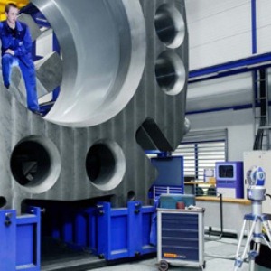
Rolling mill machines can be many stories high and include components weighing hundreds of tonnes. But using FARO tools, Siemens Metals Technologies plant makers still achieve sub-millimetre levels of accuracy.
Siemens Metals Technologies’ expertise in rolling mills dates back to 1830 when the company Davy Brothers was founded in Sheffield, England. By 1914, the company was specialised in steel works plant and machinery. A merger with an American counterpart in 1937 led to Davy-United Engineering whose principal activity was manufacturing rolling mills and related equipment. Today, Siemens Metals Technologies offers a complete range of technologies, plants & services covering the entire life cycle in the metallurgical industry to customers all over the world.
“A typical modern steel plant has an output of about 450 tonnes per hour. Interrupting production for inspection or alignment is very costly, so we need to work very fast,” explains Craig Flower, Design Engineer in the Metal Services Dept. of Siemens Metals Technologies in Sheffield.
“When we began considering our options for 3D measuring devices, one of our team suggested we look at FARO. We saw the equipment demonstrated at the Sheffield Arena Expo and FARO also gave us an on-site demonstration. We started off with a FaroArm® Platinum in 2008 and added a FARO Laser Tracker ION® in July 2011.”
Both devices have been used for inspection and alignment jobs all over the UK. For example: Steel plates coming off a mill need to be trimmed using a double-sided shear with perfectly parrallel blades: We had an alignment job where the blades were very difficult to access. Using conventional methods, the measurements and alignment would have taken several days. Using the FARO ION, it took less than one day,” smiles Craig Flower.
Another case where conventional methods can be tricky is when perpendicular alignments are required: in aluminium mills, the downcoiler needs to be exactly 90° to the aluminium sheets. Working conventionally with a theodilite, is much harder than doing the same job with a tracker.
“We were recently measuring the housing windows of a large steel plate mill”. The housing windows hold the roll chocks for the bearings and they are typically over 2 metres apart. The traditional approach – using stick micrometres is prone to error as most sticks will sag and be inaccurate over such distances. “The ION on the other hand allows us to very easily measure these distance to extremely high accuracies.”
Siemens is a global technology leader, so our customer’s really expect us to have state-of-the-art solutions. The combination of FARO hardware and software is a great productivity boost. The measurements are easily exported from CAM2 Measure 10 software to Excel for comparison, to CAD software for reverse engineering or as a PDF report for our customers.”
“All in all, FARO devices us to satisfy our customer’s expectations!”
About Siemens Metals Technologies
Siemens Metals Technologies is a 100% subsidiary of Siemens AG, the German multinational electronics and electrical engineering conglomerate. Specialising in production plants, technologies, and systems for the metallurgy sector Siemens Metals Technologies employs around 9,000 people. It currently has projects in the iron and steel industry as well as the flat-rolling sector of the aluminum industry in more than 100 countries and serves over 500 cusomers that represent 70% of global steel production.
World’s Largest Radio Astronomical Project in the Atacama Desert in Chile
In autumn 2008, several engineers and technicians from Duqueine, based near Lyon, France, which specialises in the production of high-performance composites, went to the Andean mountains in Chile to built world’s largest radio telescope.

A unique adventure for them and for the company, which has opened up a niche market through the size and precision of its components. The astronomers want the very best conditions for observing the stars. ALMA is the largest radio astronomical project in the world, situated on a unique site in the Atacama Desert on the Chajnantor Plateau, at an altitude of more than 5,000m. The site offers exceptional conditions: cloudless skies and very dry, clear air. Each antenna collects its share of radio waves which are then transmitted by cable to the permanent station, situated lower down at an altitude of around 2,900m. But the real speciality of ALMA is interferometry: the information produced by each antenna is ‘added up’, turning the 60 antennas into a single gigantic radio telescope with a size varying between 160 x 250m in a compact configuration to up to 15km in diameter, depending on the arrangement of the antennas.
The ALMA project is an international collaboration between Europe, Japan and North America in cooperation with Chile. (thanks to special vehicles, as each complete antenna weighs 100t). The European antennas are built by the AEM consortium (Alcatel Alenia Space, European Industrial Engineering SrL, MT Aerospace) and by their subcontractors including Duqueine. “It was a tough struggle to break into the market for the antenna reflector, because it is a prestigious European reference project. We landed it at the end of 2006,” says Jérôme Aubry, Head of Marketing and Sales at Duqueine, with pride.

At the heart of the antenna, the parabolic dish collects the radio waves and concentrates them on the receiver at the focal point. “The parabola has a diameter of 12m, a height of 3m and weighs 5t. The parabolic surface must not deviate from the ideal form by more than ±1.5mm. “Such precision is required as the brackets fo the micrometric control system are fixed to this surface,” explains Francis Sedeilhan, the project leader and initiator.
As soon as the contract was landed, work began. The parabola was defined geometrically (dimensions and tolerances) and functionally (rigidity, expansivity, and wind resistance for example) but it had to be designed in detail. The design office at Duqueine (around 30 engineers) tackled the job with a ‘design to cost’ approach. The material used is ACG carbon material with a very high modulus of 394 GPa. Molds had to be created on which the pre-cut panels were laid, and the production sequence had to be defined (cutting of carbon and assignment to kits, placing, baking temperature and cycle, cutting of pieces by water jet etc.). Each parabolic dish is assembled from 16 petals (slices), each created by gluing together 15 pieces. All assembly work is performed on a jig under the implacable eye of a FARO Laser Tracker X. For ease of transport, the reflector is divided into two semi-parabolas. This is the reason for the engineers’ trip to Chile. They have to ensure the two pieces fit perfectly… but for the first antenna only.