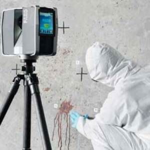
Security is a prime concern in any mine, whether gold mining or coal mining. A laser scanner can identify and record any cracks and fissures, compare these data to previous scans, and identify any areas of concern. This is an enormous contribution to mine safety and a safe work environment.
Ongoing 3D documentation of the mine, carried out by a FARO Focus3D, can prevent a mine collapse, as it instantly detects any alterations in local rock strata, so that appropriate security measures can be taken well in advance. Construction work underground, such as the digging of a new coal mine, is also made easier and safer by the use of laser aided 3D documentation.
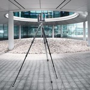
In surface mining and strip mining, used for certain types of coal and minerals, the pit also needs careful inspection. The portable FARO Focus3D can also identify specific quantities of rock and raw materials, which make it a valuable piece of modern mining equipment.
Successful scanning of Tankardstown mine in Ireland to build digital 3D models

“A project of this nature requires detailed paperwork to ensure access to the site, insurance cover for the kit and people and detailed risk and equipment assessments to ensure we could handle anything the mine could put in our way” states Deri Jones, director of Deri Jones & Associates Ltd. GSS/ DJA assembled a pretty unique team consisting of an experienced mine explorer, an ace photographer and then worked with a local group to get the kit (and them) down and back out the mine and provide safety cover. Opti-Cal Survey Equipment provided a Faro Laser Scanner Focus3D and all of the survey work was tied together
finally by a total station. The plan was to do the surface works within one full day of scanning and pano photography and then three days to complete the underground workings.
The access to the mine was achieved via an adit tunnel located some 8m above the beach, at the bottom of a steep and loose gully in the seacliff, or via a 45m shaft from the roadside. Inside the mine it was generally dry after a short thigh deep wade, but typically muddy. Another adit ran out of the cliff face further to the west, allowing a traverse loop to locate the bottom of the shaft and resection to survey points on the clifftop. Even at low tide, this meant carrying out total station work in knee deep seawater to be able to see the survey points at the top of the cliff.
Scanning
For the surface works, GSS/DJA carried out 26 scans, giving a good coverage of the buildings and allowing getting close enough to counteract the effect of the fog lying on the site, essential for the colour overlay data and panoramic photography. Underground, they recorded 56 scans using the FARO Laser Scanner Focus3D, referenced to the total station traverse using spherical targets, which was tied in to the OSI grid using the RTK GPS.
Photography
Due to the nature of the project and prior experience with getting good images underground, GSS/DJA built a LED powered light rig for their camera and made use of exposure bracketing and HDR imaging to capture as much of the fantastic colour and detail as possible. Over a thousand images were taken for the panoramic aspect of the project and cooked down to create the panoramic tours of the surface works and underground.
Deliverables
“In addition to the scan data and photos, we also received a set of mine plans from the team at Copper Coast. These were modelled up in 3D and tied in to the survey data to give a true 3D representation of the site and the workings below it. Two short animated flythroughs were created by using the scanned data from the surface and the underground working. The created panoramic tours of the site are made available online at www.coppercoastgeopark.com/ geology/tankardstown-3d-tours.html” concluded Mr. Jones.
Anderson & Associates Reduces Tunnel Interior Measurement Time by 60% Using Laser Scanners

For this project, A&A used a FARO Laser Scanner and ATS Real Reality Tunnel software to model the complete interiors of the tunnels and structures in 60% less time than is traditionally
required. “The FARO scanner turned out to be ideal for this project. Its high scanning speed made it possible to complete the job in a fraction of the time required by the conventional method.”
The Heartland Corridor is the most ambitious railroad engineering project of the last century. The project required increasing the vertical clearance of 28 tunnels and removing 24 overhead obstructions. Anderson & Associates (A&A) was hired to document the tunnels in order to check final clearances and provide a record for maintenance. Anderson & Associates (www.andassoc.com) is headquartered in Blacksburg, Virginia and has offices in West
Virginia and North Carolina as well. A&A is a professional design firm that specializes in civil and environmental engineering, surveying, planning, and landscape architecture. Since 1968, they have served as planners, designers, stewards, and advocates for institutional, municipal, state, industrial, and private sector clients. For this project, A&A used a FARO Laser Scanner and ATS Real Reality Tunnel (RRT) software to model the complete interiors of the tunnels and structures in 60% less time than is traditionally required. “In addition to saving huge amounts of time, laser scanning made it possible to model the complete interior of the tunnel,” said Neil Martin, Project Manager & Associate Vice President Surveying. “This approach gave us peace of mind that we had identified every conflict. That was lacking in the past when we were only able to measure selected cross-sections.”
Heartland Corridor project
The Heartland Corridor is a public-private partnership between Norfolk Southern (NS) railroad, the states of Virginia, West Virginia, Ohio, and the federal government to create the shortest, fastest route for double-stack container trains moving between the Port of Virginia in Norfolk and the Midwest. The line dates back to the late 19th century and traditionally has carried mostly coal traffic. New construction began in October 2007 and involved modifying 5.7 miles of tunnels through roof excavation and liner replacement, arched roof notching, and track lowering and realignment. The improvements make it possible for the line to handle double-stack container trains and provide more capacity, speed, and reliability. The new routing improves transit time from four days to three from Norfolk to Chicago and is nearly 250 miles shorter than previous circuitous routings.
A&A’s involvement with the Heartland Corridor began in 2005 when the company was selected as a subcontractor to Hatch Mott McDonald for the clearance on 28 tunnels and 8 bridges in Virginia, West Virginia, Kentucky, and Ohio. Double-stack rail transport involves stacking intermodal containers two high on railroad cars. Introduced in North America in 1984, double-stack railcars have become increasingly common. They are used for
nearly 70% of United States intermodal shipments and sharply reduce the cost per container.
Challenge of measuring tunnel profile
The centers of the tunnels were high enough nearly everywhere for the double-stack railcars, but the original tunnel roofs were roughly spherical so they obstructed the outside corners of the stacked cars. These obstructions were addressed during the construction phase of the project by cutting notches into the tunnel. Conventional equipment such as total stations were used for surveying during the design process. This traditional approach relies on visual observation to select the cross-sections that appear to be the lowest point in each tunnel section.
A total station is then used to determine the angle and distance of the points being measured to a prism. The traditional approach’s dependence on visual inspection makes it vulnerable to error as are the manual methods used to compare the resulting measurements to the train profile. For the construction phase, A&A was hired by STV/Ralph Whitehead to check the final clearances after contractors had finished their work and to document the tunnels for future maintenance. “If traditional methods would have been used to validate this project it would have been nearly impossible to ensure that the entire distance covered by the survey was free of conflicts,” said Justin Lewis, Assistant Survey Manager for A&A. “A conflict that was not addressed during the construction phase could have resulted in a train hitting the tunnel wall. This would have been very expensive to repair and also potentially dangerous for the crew of the train.”

Move to laser scanning
“In order to perform the project economically and accurately, we evaluated various laserscanning systems designed for surveying,” Lewis said. “As a phase-based scanner, the FARO Photon 120 LS is faster than the time-of-flight scanners that we looked at. This laser scanner captures data at a rate of 120,000 points per second. We also were very impressed with the RRT software that FARO bundles with this scanner. It enabled us to capture the tunnel profile, create a centerline and profile of the doublestackedcars and automatically compared the two over the entire length of the tunnel to quickly identify any conflicts.”
A&A survey technicians established control points at the starting end of the tunnel using a global positioning system (GPS). The surveyors referenced these points in the scanner coordinate system by placing a sphere mounted on a tripod on each of them. The scanner was positioned nearby on another tripod. A total station was used to determine the position of the scanner and the sphere. The scanner was then used to scan the sphere to identify the starting control point in the scanned data. The surveyors traversed through the tunnel with multiple setups using a series of tripods and spherical targets. Every time they moved the tripod and target they measured its position with the total station and then scanned it with the laser scanner to provide
a point of reference for the next batch of scan data. When the surveyors emerged from the opposite end of the tunnel they checked into the GPS to verify the accuracy of their traverse. “We found we could collect field data on the typical 1000 foot tunnel in less than 6 hours,” said Joey Conrad, Survey Technician.

Ensuring that all conflicts were identified
The total station measurements were imported into FARO Scene software and used to align the scan data taken at different positions inside the tunnel into a single frame of reference. The scan data from each tunnel was stitched into a continuous surface model of the tunnel interior using the Scene software based on the total station measurements of the scanner and round target positions. This surface model was then imported into RRT software for clearance verification. The technicians created the centerline and the silhouette of the doublestack
cars based on the design plans using AutoCAD computer-aided design (CAD) software, then exported the data as a land.xml file. This file was imported into RRT software.

On the typical curved tunnel, this template has a constantly changing vertical orientation
which would have made it very difficult to identify all of the conflicts using manual methods. RRT software, on the other hand, automatically identified the conflicts by running the template for the double-stack train across the centerline for the entire tunnel. A&A produced cross-sections
of these conflicts and provided them to the contractors for rework.
A&A then re-scanned these areas after the repairs were completed and checked them to be sure the conflicts had been eliminated. Providing a complete surface map of the tunnel interior and automatically checking it against the double-stack car contour provided a much higher level of assurance that all areas of conflict had been identified than would have been possible in the past. After the structure was verified to be conflict-free, the final drawings were provided to NS.

“The FARO scanner turned out to be ideal for this project,” Lewis said. “Its high scanning speed made it possible to complete the job in a fraction of the time required by the conventional
method. We got the job done right on schedule in spite of the challenge of only being able to
work restricted hours.” “We are seeing more and more applications for laser scanning and it’s becoming an important part of the work we do,” Lewis concluded. “For future work, we recommend scanning all tunnels and bridges prior to design. These scans would then provide a precise base for design and would be used throughout the design and construction process. The final record drawings would also provide useful maintenance documentation.”